Friday, June 20, 2014

Single Quad Loop For FM Radio DXing


N.S.HARISANKAR – VU3NSH

FM Antenna

The quad antenna have a gain of 1.4 dB over a dipole and also operate over a relatively wide frequency. Quad antenna dipole to form 1/4 lambda each side makes a square. American Radio Amateur (HAM) Clarence C. Moore, W9LZX developed this system in 1939 for the Missionary Radio Station HCJB at Quito of Ecuadaor (South America). The altitude of the station was over 10,000 feet in Andes. The station was operated in 25 m band SW with TX power of 10 KW. The band width of a single dipole is quite narrow. The quad loop is having high gain and less corona discharges etc. The half lambda folded dipole impedance is 288 Ohms (300 Ohms) and this quad loop is having 125 Ohms feed impedance. Due to low impedance of the quad, there is no need of any matching, for a general FM receiver system.

Connecting a folded dipole (gain : 2.14 dB, 1.45 m long and 300 Ohms) to a FM receiver of 75 Ohms input, without any matching, its efficiency becomes to 65% (VSWR-4) and a 125 Ohms quad at 75 Ohms receiver without matching it will get 95% efficiency (VSWR-1.66) with an extra gain of 1.4 dB over a folded dipole. Due to this 3.54 dB gain from a quad loop there will be a terrific FM Radio reception. Using a split dipole, having 75 Ohms feed impedance, there will be correct match of 75 Ohms FM receiver system. But one of the element will be isolated and it makes static and lightning problems. if we ground the cable braid (shield), the entire quad or foled dipole antenna system get grounded and it avoid the threat from static or lightning effects.

FM Radio allocation in India is from 88 MHz to 108 MHz. So the mid frequency is 98 MHz. The equation for getting the wave length of the conductor is (300 x 0.95) / 98 MHz. i.e. 2.908163 meters. If we divide this value by 4 we can get the Quarter Lambda length. i.e. 72.70 cm, we can take it as 73 cm or 74 cm. Due to skin effect of VHF frequency the element should be a tube having more than 4 mm dia or use 3/8th tube for getting good efficiency.

Connection To Radio

Connect with proper connector as per your FM Radio. If there is no external antenna input in your Radio, then connect the Ground (Shield) to Battery negative and other line to the telescopic aerial.

References

[1] en.wikipedia.org/wiki/quad_antenna
[2] en.wikipedia.org/wiki/HCJB
[3] www.cubex.com/history.htm

FM Radio Rectangle Super Gainer (Moxon Antenna)


It is not much popular antenna but much old design!! The original name of this antenna is Two Element Driven Arrays. In 1952 Les Moxon published this Genius Design in QST July Issue. It is a rectangular shaped two elements with a closed spacing of 0.18 lambda. The ends of the two element are folded in 90 degree face to face with a critical spacing of each other. This rectangle beam is popular among ham radio operators as Moxon Antenna. Few hams are using it for HF (SW) bands. It is a directional type antenna with a wide angle of 136 degree typical aperture and with a very good band width. (The Radiation pattern is like Kidney shape, and it is the same in reciprocity) . Due to the bend at the ends of each element and due to the critical spacing of each tips it is a capacity loaded, and it yields the wide bandwidth and low SWR levels. It is a low take of angle type of 14 degree or low typically, and it pick ups maximum stations from planes. Therefore I decided to make this antenna in FM Radio band to receive the spectrum of 88 MHz to 108 MHz.

One of my SWL Murali (School Teacher), who is a good listener of MW-SW-FM bands, asked to make an antenna which gives directivity, wide angle and very high gain for his own use. For this purpose I converted the basic design to 3 meter BC band radio use. I made this rectangle beam (Moxon) with 3/8 th aluminum tube. For the critical spacing of each element tips, I made hilum insulators as a prototype. The feed point is connected with a simple cable TV connector called F-Connector which is economical and easily available at the local market.

While testing, if it is pointing to eastern direction it will pick the signals from East and also it will pick the signal from South East and North East due to its wide angle aperture. More over the beauty of this antenna is the two elements will give 9 dBi + gain. Typically this antenna gives 7 to 14 dBi depending upto the accuracy of the construction and it can be a wide angle of 100 degrees to 136 degrees, the F/B ratio can be 30 dB to 40 dB. This antenna should be mounted at least 1 lambda of the operating frequency above the ground level. i.e., 3 meter (10 ft). For excellent performance, the height should be 25 to 30 ft. and the surrounding clearance should be maximum. Do not test this antenna near to any metallic objects and that will reduce its performance drastically.

For receiving FM BC Bands you can connect any good quality and low loss 75 ohms coaxial cable to the driven elements at the middle point of this antenna. No matching is required like balun, gamma, hair pin etc. and therefore no question of matching loss. Refer the following figures for getting specific ideas about the antenna and its construction. A well constructed rectangle beam antenna is equivalent to a four element yagi antenna.

In the next part we will reveal some antenna engineering about rectangle beam for 2 metre ham band operation.

FM bc band - mesurements for 100 Mhz
Fig. 1. FM bc band - mesurements for 100 Mhz. This measurements are for 3/8 Aluminium tube (9.5 mm OD)

FM bc band - mesurements for 100 Mhz
Fig. 2. Rectangle beam (Moxon) plot

Thursday, June 19, 2014

1.3W VHF RF Amplifier 2SC1970 88-108 MHz


    1.3W VHF RF Amplifier 2SC1970 88-108 MHz

    1.3W VHF RF Amplifier 2SC1970 88-108 MHz


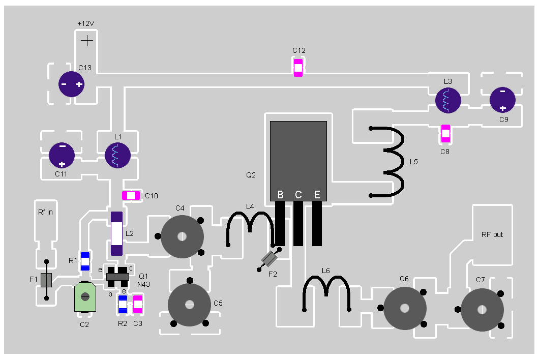
    This RF power amplifier is based on the transistor 2SC1970 and 2N4427. The output power is about 1.3W and the input driving power is 30-50mW. It will still get your RF signal quit far and I advice you to use a good 50 ohm resistor as dummy load. To tune this amplifier you can either use a power meter/wattmeter, SWR unit or you can do using a RF field meter.

    1.3W VHF RF Amplifier 2SC1970 88-108 MHz

    RF Amplifier Assembly


    Good grounding is very important in a RF system. I use bottom layer as Ground and I connect it with the top with wires to get a good grounding. Make sure you have some cooling at the transistor. In my case I put the 2SC1970 close to the PCB to handle the heat. With good tuning the transistor shouldn't become hot.


    RF Amplifier Printed Circuit Board


    You can download a pdf file which is the black PCB. The PCB is mirrored because the printed side side should be faced down the board during UV exposure. To the right you will find a pic showing the assembly of all components on the same board.This is how the real board should look when you are going to solder the components. It is a board made for surface mounted components, so the copper is on the top layer. I am sure you can still use hole mounted components as well.
    Grey area is copper and each component is draw in different colors all to make it easy to identify for you. The scale of the pdf is 1:1 and the picture at right is magnified with 4 times. Click on the pic to enlarge it.


    Low-Pass Filter


    Some of you might want to add a low-pass filter at the output. I have not added any extra low pass filter in my construction because I don't think it is needed. You can easy find several homepages about low pass filter and how to build them.

    1.3W VHF RF Amplifier 2SC1970 88-108 MHz


Homebrewed Off-Center Fed Dipole


Ocfd.jpg

Building A Homebrewed Off-Center Fed Dipole Scanner Antenna.

Aluminum/copper tubing construction:

You will need to check the fit of the tubing with the T connector and the caps while you are at the store. One combination that fits nicely is 3/4" copper pipe with 3/4" CPVC fittings (not to be confused with 3/4" PVC fittings which will be too large). The tubing/connector is held in place with 2 stainless steel sheet metal screws for connecting the balun to each element.

Find a "U" bolt to fit your mast. Drill two holes in the support pipe to fit the U bolt.The support pipe is 18" from the "T" to the mast.

Remember, bandwidth increases as diameter of the elements increases. I think, if I remember correctly, at the hardware store, that a few CPVC fittings will fit copper tubing perfectly!

Some say that the 18" element on top mounted works best,Some like the 48" element on top.It does'nt matter,it works the same.

If you use the copper tubing,be sure to paint it with some good,non-conductive paint.I used to paint mine light grey. -Have fun! (Teraycoda)

For an alternate/temporary mounting option, drill a hole in one of the end caps and put in an eye bolt with a nut on the underside of the cap to secure. Be sure to secure this end cap to the copper tubing somehow, perhaps with an additional small stainless sheet metal screw. Be sure that the eye bolt itself doesn't make electrical contact with the tubing. Also, drill a small weep hole in the bottom end cap to allow any moisture to escape that may accumulate inside. Use the eye bolt and some rope to pulley the antenna up high in a tree, or use a hook to hang it somewhere. Give careful consideration to safety and grounding depending on your particular usage scenario. (Qdude)


Variation for Off-Center Fed Dipole Using Simple Wire and 75 to 300 ohm TV Balun Transformer

Offset dipole scanner antenna.jpg

Electrically, this version is the same as the one using copper tubing (above) but can be assembled quickly and is quite portable. While not as broadbanded as an OCFD using copper tubing or other metal with a larger diameter, the OCFD made from simple wire turns in great receive performance in all the commonly scanned bands, as reported here on RR in multiple message threads.

The legs/ends of the dipole are simple bell wire and shown here coiled up. Uncoil them and hang them vertically; doesn't matter if the long or short leg is at the top... works the same either way. The wire terminal lugs shown at the end of the legs of the dipole antenna should NOT be connected electrically to the wires - just crimp them on over the wire insulation. They are used as convenient hangers for the antenna, and not meant for electrical connection. Obviously, the lugs at the TV transformer/balun ends of the wire should be stripped before crimping on the terminal lugs to ensure contact with the antenna wires when you attach the TV transformer. Ensure the 75 ohm coax feedline that you connect from the balun/transformer runs away from the antenna at as near a 90 degree angle as possible.