
Saturday, June 28, 2014
Single transistor Miniature FM transmitter with VCO
This simple transmitter allows you to broadcast on FM radio band (VHF) 87.5 - 108 MHz. It consists of a simple oscillator with silicon planar RF PNP transistor. Directly to the oscillator an antenna is connected. Due to the large amplitude of RF voltage is sufficient antenna length of about 5-10 cm. I used insulated 7cm long copper wire 1mm diameter. I eliminated the tuning capacitor, which is usual for most bugs and miniature transmitters, because this greatly complicates the tuning. From my own experience I know that if you get closer to such capacitor, the operating frequency is changed. That's why I chose to use the voltage tuning using the Voltage Controlled Oscillator (VCO). Instead of tuning capacitor the varicap (capacitance diode) is used, which changes its capacity by changing the reverse DC voltage. We can tune the operating frequency by changing the DC voltage using the trimmer P1. Varicap also provides frequency modulation.
Tuning: Set P1 to the center. Turn on the FM radio and tune it to an unoccupied frequency in the 87.5 - 108 MHz band. You will hear a noise. Turn on the transmitter and the first tune the operating frequency of roughly by stretching turns in the coil L1. Then fine-tune the frequency using P1. Proper tuning is indicated by the radio getting silent. You can then connect audio source to the input (such as cassette player, CD or MP3 player, record player, audio output of PC or laptop, etc.). It is also possible to tune while already connected to the signal source. The circuit can be powered from 5V USB port available on your PC or laptop.
Inductor L1 is airborne and has six turns of 0.5 mm diameter wire wound on 3 mm diameter. Varicap is arbitrary, which covers the range of about 5-20pF, such as BB105, KB105, KB109. I used the varicap KB109G made by Tesla with yellow paint on the cathode. The transistor is a high-frequency planar PNP type, for example, BF970, BF979, or simmilar. You can also use a transistor with different type of case. The disadvantage of the circuit is sensitivy to changes in supply voltage (it is changing the varicap voltage and thus the operating frequency). The antenna is connected directly to the oscillator, so if you touch it or placing it near the conductive object, the frequency shifts. At its simplicity, however, the circuit works surprisingly well and the range is about 20 to 100 meters. You can use power supply of 5-12V or a battery. There should be no ripple in the supply voltage, otherwise it may be heard in the receiver.
Warning: Broadcasting on VHF-FM band may be illegal in your country. Author does not take any responsibility for your possible legal penalties for illegal broadcast or due to abuse of the bug for illegal purposes! Everything you do at your own risk.
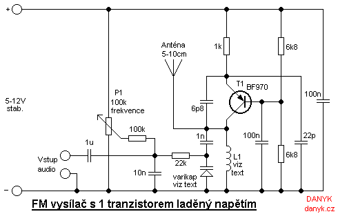
The schematic of the Single transistor Miniature FM transmitter with VCO
88-108 MHz FM covert listening device (bug)
This is a simple listening bug. The signal can be tuned on any FM radio. The first transistor (in the circuit diagram on the left) works as an oscillator (in Colpitts connection), the frequency depends on: trimmer capacitor, inductor (with 4 turns wound on 5mm diameter, no core), varicap and capacitor between collector and emitter of the first transistor. Low frequency signal from the electret microphone affects varicap voltage and thus its capacity. Varicap affectc the oscillator frequency and thus modulates the carrier wave. The second transistor acts as an amplifier and also contributes to separation of the antenna from the oscillator, thereby improving the frequency stability.
How to use the bug: Turn on the FM radio and connect the bug to voltage 9-12 VDC and try to tune the radio frequency bugs. If the bug is near the radio and the radio is well tuned, you can hear feedback whistling. Range of this bug is about 20 to 100m (66 to 330 feet). The antenna is cca 10 - 30cm (1/3 - 1 feet) wire.
Warning: Broadcasting on VHF-FM band may be illegal in your country. Author does not take any responsibility for your possible legal penalties for illegal broadcast or due to abuse of the bug for illegal purposes! Everything you do at your own risk.
5W1.5W 88-108Mhz FM Transmitter 14MHz (20m) AM Transmitter
This transmitter is designed to transmit sound (music, speech, ...) at frequencies 88-108MHz with a frequency modulation (FM). Its RF power is about 1.5 W. The first transistor is used as an RF oscillator. Varicap allows the oscillator frequency shifting and thus its frequency modulation and frequency tuning via potentiometer. Varicap may not be the BB105, it can be BB409, BB109G, KB109G or other type. The second transistor is the power output stage. The output signal goes through a filter to remove harmonics and then it enters antenna, eg dipole or Yagi antenna (it has better directivity). Power transistor is on the heatsink with min. 100 cm2 area. Coils are air, wire diameter of 0.6 mm wound on 5 mm.
Warning! Operating this transmitter without permission is illegal.

1.5W 88-108Mhz FM power Transmitter schematic (note: "z" means number of turns)
Saturday, June 21, 2014
Simple FM Receiver
Frequency modulation is used in radio broadcast in the 88-108MHz VHF band. This bandwidth range is marked as FM on the band scales of radio receivers, and the devices that are able to receive such signals are called FM receivers. The FM radio transmitter has a 200kHz wide channel. The maximum audio frequency transmitted in FM is 15 kHz as compared to 4.5 kHz in AM. This allows much larger range of frequencies to be transferred in FM and thus the quality of FM transmission is significantly higher than of AM transmission.
Here’s a simple FM receiver with minimum components for local FM reception. Transistor BF495 (T2), together with a 10k resistor (R1), coil L, 22pF variable capacitor (VC), and internal capacitances of transistor BF494 (T1), comprises the Colpitts oscillator. The resonance frequency of this oscillator is set by trimmer VC to the frequency of the transmitting station that we wish to listen. That is, it has to be tuned between 88 and 108 MHz. The information signal used in the transmitter to perform the modulation is extracted on resistor R1 and fed to the audio amplifier over a 220nF coupling capacitor (C1).

You should be able to change the capacitance of the variable capacitor from a couple of picofarads to about 20 pF. So, a 22pF trimmer is a good choice to be used as VC in the circuit. It is readily available in the market. If you are using some other capacitor that has a larger capacitance and are unable to receive the full FM bandwidth (88-108 MHz), try changing the value of VC. Its capacitance is to be determined experimentally.
The self-supporting coil L has four turns of 22 SWG enamelled copper wire, with air core having 4mm internal diameter. It can be constructed on any cylindrical object, such as pencil or pen, having a diameter of 4 mm. When the required number of turns of the coil has reached, the coil is taken off the cylinder and stretched a little so that the turns don’t touch each other.
Capacitors C3 (100nF) and C10 (100µF, 25V), together with R3 (1k), comprise a band-pass filter for very low frequencies, which is used to separate the low-frequency signal from the high-frequency signal in the receiver.You can use the telescopic antenna of any unused device. A good reception can also be obtained with a piece of isolated copper wire about 60 cm long. The optimum length of copper wire can be found experimentally.
The performance of this tiny receiver depends on several factors such as quality and turns of coil L, aerial type, and distance from FM transmitter. IC LM386 is an audio power amplifier designed for use in low-voltage consumer applications. It provides 1 to 2 watts, which is enough to drive any small-size speaker. The 22k volume control (VR) is a logarithmic potentiometer that is connected to pin 3 and the amplified output is obtained at pin 5 of IC LM386. The receiver can be operated off a 6V-9V battery.
VHF FM Transmitter MAX2606
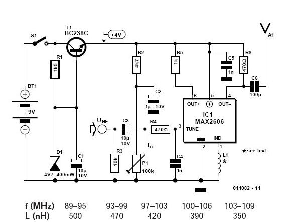
If you want to be independent of the local radio stations for testing VHF receivers, you need a frequency-modulated oscillator that covers the range of 89.5 to 108 MHz — but building such an oscillator using discrete components is not that easy. Maxim now has available a series of five integrated oscillator building blocks in the MAX260x series which cover the frequency range between 45 and 650 MHz. The only other thing you need is a suitable external coil, dimensioned for the midrange frequency.
Stereo FM Transmitter with BA1404
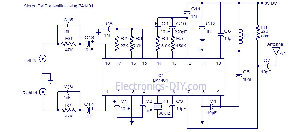
A high quality stereo FM transmitter circuit is shown here. The circuit is based on the IC BA1404 from ROHM Semiconductors. BA1404 is a monolithic FM stereo modulator that has built in stereo modulator, FM modulator and RF amplifier. The FM modulator can be operated from 76 to 108MHz and power supply for the circuit can be anything between 1.25 to 3 volts. In the circuit R7, C16, C14 and R6, C15, C13 forms the pre-emphasis network for the right and left channels respectively. This is done for matching the frequency response of the FM transmitter with the FM receiver. Inductor L1 and capacitor C5 is used to set the oscillator frequency. Network C9,C10, R4,R5 improves the channel separation. 38kHz crystal X1 is connected between pins 5 and 6 of the IC. Composite stereo signal is created by the stereo modulator circuit using the 38kHz quartz controlled frequency.
FM Transmitter with 2N2218
Here's simple FM transmitter circuit using medium power 2N2218 transistor. Micropohone is of electret type that connects to two input terminals and the antenna should be a copper wire from 15 to 40 cm. Below is schematic circuit of the fm transmitter.
Phone Spy Transmitter
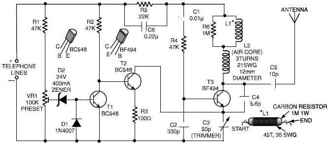
Here is a very simple telephone broadcaster transmitter which can be used to eavesdrop on a telephone conversation. The circuit can also be used as a wireless telephone amplifier. One important feature of this phone transmitter is that the circuit derives its power directly from the active telephone lines, and thus avoids use of any external battery or other power supplies.
1.5V FM Transmitter
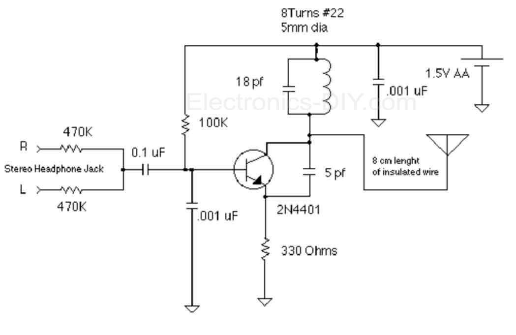
The objective of this 1.5V FM Broadcast Transmitter design is to provide a simple low-power transmitter solution for broadcasting audio from various audio sources. This transmitter accepts stereo input via two 470K resistors. Since there is no audio level control on the input, the audio level out from the source needs to be adjusted. Or, you can just add a 10k as an input level control. Transmitter's frequency, as built is tunable via spreading or compressing the coil to the desired frequency, and the coil can be glued down. If you want to make one that's tunable, it might be easiest to reduce the 18 pf capacitor and put a small trimmer capacitor in parallel with the inductor (across the reduced value capacitor). Voltage variable capacitors would be an nice alternative to a mechanical variable capacitor but they don't offer much tuning range with only a 1.5V power supply.
Coil less FM Transmitter
The RF oscillator using the inverter N2 and 10.7Mhz ceramic filter is driving the parallel combination of N4 to N6 through N3.Since these inverters are in parallel the output impedance will be low so that it can directly drive an aerial of 1/4th wavelength. Since the output of N4-N6 is square wave there will be a lot of harmonics in it. The 9th harmonics of 10.7Mhz (96.3Mhz) will hence be at the center of the FM band. N1 is working as an audio amplifier. The audio signals from the microphone are amplified and fed to the varicap diode. The signal varies the capacitance of the varicap and hence varies the oscillator frequency which produce Frequency Modulation.
1W Long Range FM Transmitter
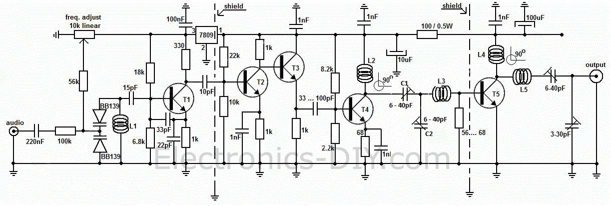
Long range, very stable, harmonic free, FM transmitter circuit which can be used for FM frequencies between 88 and 108 MHz. With good antenna transmitter can cover 5km range. It has a very stable oscillator because it uses LM7809 voltage regulator which is a 9V stabilized power supply for T1 transistor. Frequency adjustment is achieved by using the 10K linear potentiometer. The output power of this long range RF transmitter is around 1W but can be higher if you use transistors like KT920A, BLX65, BLY81, 2N3553, 2SC1970 or 2SC1971.
4 Transistor FM Transmitter
This circuit provides an FM modulated signal with an output power of around 500mW. The input microphone pre-amp is built around a couple of 2N3904 transistors (Q1/Q2), and audio gain is limited by the 5k preset trim potentiometer. The oscillator is a colpitt stage, frequency of oscillation governed by the tank circuit made from two 5pF ceramic capacitors and the L2 inductor. The output stage operates as a 'Class D' amplifier, no direct bias is applied but the RF signal developed across the 3.9uH inductor is sufficient to drive this stage. The emitter resistor and 1k base resistor prevent instability and thermal runaway in this stage.
1 Watt FM Transmitter Amplifier
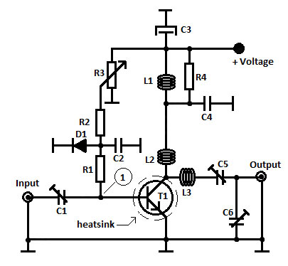
This is a 1 Watt FM Transmitter amplifier with a good design that can be used to amplify a RF signal in the 88 – 108 MHz band. It is very sensitive if you use good RF power amplifier transistors, trimmers and coils. It has a power amplification factor of 9 to 12 dB (9 to 15 times). At an input power of 0.1W the output will be 1W. You must choose T1 transistor depending on applied voltage. If you have a 12V power supply then use transistors like: 2N4427, KT920A, KT934A, KT904, BLX65, 2SC1970, BLY87. At 18 to 24V power supply you must use transistors like: 2N3866, 2N3553, KT922A, BLY91, BLX92A. You may use 2N2219 at 12V but you will get an output power of 0.4W maximum.
18W FM Transmitter
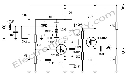
Here's FM transmitter for commercial FM band that provides 18 watts of power. Since the electronic diagram is too large we decided to divide it into two parts. The first part is the actual FM transmitter while the second part is 18W RF amplifier. The circuit should be built on an epoxy printed circuit board with the upper face components reserved for interconnecting tracks and the bottom solder to the ground plane. If powered by 14V and 2.5A transmitter outputs 15W of power, whereas 18V and 3.5A will provide 18W. BB110 variable capacitor connected to the collector of transistor BF199 adjusts the transmission frequency of the circuit. 2K2 potentiometer serves as fine tuning. Once the output frequency is adjusted amplifier variable capacitors must be adjusted for maximum output power one stage at a time. All adjustments must be made with 50 Ohm dummy load connected to the output of transmitter.


Friday, June 20, 2014
Single Quad Loop For FM Radio DXing
N.S.HARISANKAR – VU3NSH

The quad antenna have a gain of 1.4 dB over a dipole and also operate over a relatively wide frequency. Quad antenna dipole to form 1/4 lambda each side makes a square. American Radio Amateur (HAM) Clarence C. Moore, W9LZX developed this system in 1939 for the Missionary Radio Station HCJB at Quito of Ecuadaor (South America). The altitude of the station was over 10,000 feet in Andes. The station was operated in 25 m band SW with TX power of 10 KW. The band width of a single dipole is quite narrow. The quad loop is having high gain and less corona discharges etc. The half lambda folded dipole impedance is 288 Ohms (300 Ohms) and this quad loop is having 125 Ohms feed impedance. Due to low impedance of the quad, there is no need of any matching, for a general FM receiver system.
Connecting a folded dipole (gain : 2.14 dB, 1.45 m long and 300 Ohms) to a FM receiver of 75 Ohms input, without any matching, its efficiency becomes to 65% (VSWR-4) and a 125 Ohms quad at 75 Ohms receiver without matching it will get 95% efficiency (VSWR-1.66) with an extra gain of 1.4 dB over a folded dipole. Due to this 3.54 dB gain from a quad loop there will be a terrific FM Radio reception. Using a split dipole, having 75 Ohms feed impedance, there will be correct match of 75 Ohms FM receiver system. But one of the element will be isolated and it makes static and lightning problems. if we ground the cable braid (shield), the entire quad or foled dipole antenna system get grounded and it avoid the threat from static or lightning effects.
FM Radio allocation in India is from 88 MHz to 108 MHz. So the mid frequency is 98 MHz. The equation for getting the wave length of the conductor is (300 x 0.95) / 98 MHz. i.e. 2.908163 meters. If we divide this value by 4 we can get the Quarter Lambda length. i.e. 72.70 cm, we can take it as 73 cm or 74 cm. Due to skin effect of VHF frequency the element should be a tube having more than 4 mm dia or use 3/8th tube for getting good efficiency.

Connect with proper connector as per your FM Radio. If there is no external antenna input in your Radio, then connect the Ground (Shield) to Battery negative and other line to the telescopic aerial.
References
[1] en.wikipedia.org/wiki/quad_antenna
[2] en.wikipedia.org/wiki/HCJB
[3] www.cubex.com/history.htm
FM Radio Rectangle Super Gainer (Moxon Antenna)
It is not much popular antenna but much old design!! The original name of this antenna is Two Element Driven Arrays. In 1952 Les Moxon published this Genius Design in QST July Issue. It is a rectangular shaped two elements with a closed spacing of 0.18 lambda. The ends of the two element are folded in 90 degree face to face with a critical spacing of each other. This rectangle beam is popular among ham radio operators as Moxon Antenna. Few hams are using it for HF (SW) bands. It is a directional type antenna with a wide angle of 136 degree typical aperture and with a very good band width. (The Radiation pattern is like Kidney shape, and it is the same in reciprocity) . Due to the bend at the ends of each element and due to the critical spacing of each tips it is a capacity loaded, and it yields the wide bandwidth and low SWR levels. It is a low take of angle type of 14 degree or low typically, and it pick ups maximum stations from planes. Therefore I decided to make this antenna in FM Radio band to receive the spectrum of 88 MHz to 108 MHz.
One of my SWL Murali (School Teacher), who is a good listener of MW-SW-FM bands, asked to make an antenna which gives directivity, wide angle and very high gain for his own use. For this purpose I converted the basic design to 3 meter BC band radio use. I made this rectangle beam (Moxon) with 3/8 th aluminum tube. For the critical spacing of each element tips, I made hilum insulators as a prototype. The feed point is connected with a simple cable TV connector called F-Connector which is economical and easily available at the local market.
While testing, if it is pointing to eastern direction it will pick the signals from East and also it will pick the signal from South East and North East due to its wide angle aperture. More over the beauty of this antenna is the two elements will give 9 dBi + gain. Typically this antenna gives 7 to 14 dBi depending upto the accuracy of the construction and it can be a wide angle of 100 degrees to 136 degrees, the F/B ratio can be 30 dB to 40 dB. This antenna should be mounted at least 1 lambda of the operating frequency above the ground level. i.e., 3 meter (10 ft). For excellent performance, the height should be 25 to 30 ft. and the surrounding clearance should be maximum. Do not test this antenna near to any metallic objects and that will reduce its performance drastically.
For receiving FM BC Bands you can connect any good quality and low loss 75 ohms coaxial cable to the driven elements at the middle point of this antenna. No matching is required like balun, gamma, hair pin etc. and therefore no question of matching loss. Refer the following figures for getting specific ideas about the antenna and its construction. A well constructed rectangle beam antenna is equivalent to a four element yagi antenna.
In the next part we will reveal some antenna engineering about rectangle beam for 2 metre ham band operation.

Fig. 1. FM bc band - mesurements for 100 Mhz. This measurements are for 3/8 Aluminium tube (9.5 mm OD)

Fig. 2. Rectangle beam (Moxon) plot
Thursday, June 19, 2014
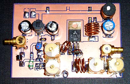
1.3W VHF RF Amplifier 2SC1970 88-108 MHz
![]()
This RF power amplifier is based on the transistor 2SC1970 and 2N4427. The output power is about 1.3W and the input driving power is 30-50mW. It will still get your RF signal quit far and I advice you to use a good 50 ohm resistor as dummy load. To tune this amplifier you can either use a power meter/wattmeter, SWR unit or you can do using a RF field meter.
RF Amplifier Assembly
Good grounding is very important in a RF system. I use bottom layer as Ground and I connect it with the top with wires to get a good grounding. Make sure you have some cooling at the transistor. In my case I put the 2SC1970 close to the PCB to handle the heat. With good tuning the transistor shouldn't become hot.
RF Amplifier Printed Circuit Board
You can download a pdf file which is the black PCB. The PCB is mirrored because the printed side side should be faced down the board during UV exposure. To the right you will find a pic showing the assembly of all components on the same board.This is how the real board should look when you are going to solder the components. It is a board made for surface mounted components, so the copper is on the top layer. I am sure you can still use hole mounted components as well.
Grey area is copper and each component is draw in different colors all to make it easy to identify for you. The scale of the pdf is 1:1 and the picture at right is magnified with 4 times. Click on the pic to enlarge it.
Low-Pass Filter
Some of you might want to add a low-pass filter at the output. I have not added any extra low pass filter in my construction because I don't think it is needed. You can easy find several homepages about low pass filter and how to build them.

Homebrewed Off-Center Fed Dipole

Building A Homebrewed Off-Center Fed Dipole Scanner Antenna.
Aluminum/copper tubing construction:
You will need to check the fit of the tubing with the T connector and the caps while you are at the store. One combination that fits nicely is 3/4" copper pipe with 3/4" CPVC fittings (not to be confused with 3/4" PVC fittings which will be too large). The tubing/connector is held in place with 2 stainless steel sheet metal screws for connecting the balun to each element.
Find a "U" bolt to fit your mast. Drill two holes in the support pipe to fit the U bolt.The support pipe is 18" from the "T" to the mast.
Remember, bandwidth increases as diameter of the elements increases. I think, if I remember correctly, at the hardware store, that a few CPVC fittings will fit copper tubing perfectly!
Some say that the 18" element on top mounted works best,Some like the 48" element on top.It does'nt matter,it works the same.
If you use the copper tubing,be sure to paint it with some good,non-conductive paint.I used to paint mine light grey. -Have fun! (Teraycoda)
For an alternate/temporary mounting option, drill a hole in one of the end caps and put in an eye bolt with a nut on the underside of the cap to secure. Be sure to secure this end cap to the copper tubing somehow, perhaps with an additional small stainless sheet metal screw. Be sure that the eye bolt itself doesn't make electrical contact with the tubing. Also, drill a small weep hole in the bottom end cap to allow any moisture to escape that may accumulate inside. Use the eye bolt and some rope to pulley the antenna up high in a tree, or use a hook to hang it somewhere. Give careful consideration to safety and grounding depending on your particular usage scenario. (Qdude)
Variation for Off-Center Fed Dipole Using Simple Wire and 75 to 300 ohm TV Balun Transformer

Electrically, this version is the same as the one using copper tubing (above) but can be assembled quickly and is quite portable. While not as broadbanded as an OCFD using copper tubing or other metal with a larger diameter, the OCFD made from simple wire turns in great receive performance in all the commonly scanned bands, as reported here on RR in multiple message threads.
The legs/ends of the dipole are simple bell wire and shown here coiled up. Uncoil them and hang them vertically; doesn't matter if the long or short leg is at the top... works the same either way. The wire terminal lugs shown at the end of the legs of the dipole antenna should NOT be connected electrically to the wires - just crimp them on over the wire insulation. They are used as convenient hangers for the antenna, and not meant for electrical connection. Obviously, the lugs at the TV transformer/balun ends of the wire should be stripped before crimping on the terminal lugs to ensure contact with the antenna wires when you attach the TV transformer. Ensure the 75 ohm coax feedline that you connect from the balun/transformer runs away from the antenna at as near a 90 degree angle as possible.
Subscribe to:
Posts (Atom)