Wednesday, April 30, 2014
Monday, April 28, 2014
Using 555 as FM transmitter

The integrated circuit 555 has no limits, this FM transmitter circuit,
the IC 555 is designed as an stable multivibrator as usual. But the
tension control pin is used to connect a piezoelectric element instead
of the capacitor disk. The piezoelectric element generates a voltage and
the output pin is connected to an antenna wire 30 inches for the
transmission of signals.Just tap the piezo element and you can hear the
sound on an FM radio station. The range is very short.
100MHZ VHF FM Transmitter
This transmitter circuit has been built and tested and it has a range of a few feet if no antenna is connected.
- The input transducer is an electret microphone. R1 provides DC power for the FET pre-amplifier built into the electret microphone.
- Audio signals cause changes in the FET current and this causes the voltage across R1 to vary.
- C1 couples the audio AC output from the microphone to the next amplifier stage. This coupling capacitor blocks DC potentials.
- R2 and R3 form a voltage divider providing a 6 Volt line (50% of the power supply).
- C2 is a decoupling capacitor. It guarantees that there are no AC voltages at point A in the circuit.
- R4 ensures that the DC voltage is 6 Volts at the non inverting input (pin 3) of the op amp.
- R5 and R6 control the gain of the op amp.
- Gain = 1 + Rf / R1 = 1 + 220 / 3.3 = 67.7
- In a normal op amp circuit, R5 would be connected to ground and a -12V supply line would be needed.
- In this circuit, R5 is connected to point A and the -12 Volt line is not needed.
- The op amp is a 741 but almost any pin compatible device should work.
- R7 couples the op amp audio output to D1 and provides DC reverse bias across D1.
- R7 is large to prevent RF signals escaping from the oscillator circuit.
- D1 is a 5 amp rectifier diode. It is being used as a variable reactance diode. When the diode is reverse biased, virtually no current flows but there is some capacitance. If the reverse bias voltage is increased, the capacitance decreases. This makes a voltage controlled capacitor. The DC output of the op amp reverse biases the diode. The audio output from the op-amp varies the bias voltage and causes the capacitance of the diode to change. This changes the transmission frequency. In this way, Frequency Modulation is produced. Various diodes were tried and this one worked best. It is possible to buy varactor diodes which would work better.
- D1, C3 and C4 with the coil form a tuned circuit which resonates at about 100 MHz in the middle of the FM radio band.
- The MPF102 (available from Farnell Electronics) is connected as a source follower with a useful current gain.
- The source current flows through one turn of the four turn coil. This current induces a voltage across the whole coil and this is fed to the gate. This is positive feedback and the circuit oscillates at the resonant frequency of the tuned circuit.
- This is a Hartley oscillator with modified tuning capacitors to allow frequency modulation with the varactor diode.
- C4 is a fixed 22 pF capacitor. The circuit would be easier to get working with a trimmer capacitor covering 5 to 30 pF.
- C5 is a decoupling capacitor. It prevents RF voltages on the FET drain.
- R8 limits the DC current through the FET and ensures the device operates inside safe limits.
- D2 is a polarity protection diode. It protects the circuit if the power supply is connected the wrong way round.
- C6 and C7 are decoupling capacitors. C7 works well at low (audio) frequencies and C6 works well at VHF radio frequencies.
VHF FM Power Meter

This is a actual accessible
apparatus that will acquaint you if your transmitter's oscillator is
alive properly. If RF arresting is transmitted the LED will illuminate.
Besides that, it will additionally accord you a quick beheld way to
analysis how abundant ability is actuality transmitted. I awful acclaim
that you accept the transmitter and ability beat on the aforementioned
PCB. If you like to agreement a lot, you will acknowledge this bargain
but evidently accessible addition.
TX200 VFO/VCO FM transmitter.


Here is the latest and abundantly bigger TX200 VFO/VCO FM transmitter.
The best able transmitter to date that can be angry into aerial
allegiance stereo PLL based 200mW FM transmitter. It is a absolute ambit
for transmitting your music about the abode and yard. TX200 uses alone
two coils; one in the oscillator and the added one in the 200mW VHF
amplifier so it should be adequately accessible for anyone to build. It
additionally includes congenital pre-emphasis and C5 for added complete
quality. While accumulating the transmitter affliction charge be taken
to accomplish abiding that C1 is anon affiliated to L1 and C9 to L2.
These caps annihilate the distortions anatomy the DC accumulation and
advance the complete affection greatly. 9V voltage accumulation is
additionally actual important because it provides the exact bulk of
accepted to Q1 to aftermath loud and bright complete quality. I
achievement that you'll accept as abundant fun as I had while
architecture this transmitter.
10 WATT FM POWER AMPLIFIER
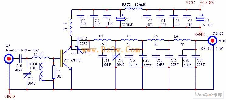
This power amplifier can extend 1-2W、88-108MHZ FM transmitter power to
10-15W.It uses single pipe c class amplifier and low-pass filter.It has
higher conversion efficiency andstrong suppersion of considered wave.
Principle Figure
The circuit is showed as above.It adopts high-power transmitting tube
C1972 and parameters are as follows:175MHZ,4A,25W,power gain ≥8.5db.As
the pictures'parameters,the work center frequency is about 98MHZ.When
the input radio-frequency power is about 2W,the rating output can reach
15W.The center frequency of former stage adjusts part of components to
make sure that any frequency port among 88~108MHZ can reach rating value
when it outputs.
USB FM Transmitter

To keep the fm transmitter circuit simple as well as compact, it was
decided to use a chip made by Maxim Integrated Products, the MAX2606.
This IC from the MAX2605-MAX2609 series has been specifically designed
for low-noise RF applications with a fixed frequency. The VCO (Voltage
Controlled Oscillator) in this IC uses a Colpitts oscillator circuit.
The variable-capacitance (varicap) diode and feedback capacitors for the
tuning have also been integrated on this chip, so that you only need an
external inductor to fix the central oscillator frequency.
It is possible to fine-tune the frequency by varying the voltage to
the varicap. Not much is demanded of the inductor, a type with a
relatively low Q factor (35 to 40) is sufficient according to Maxim. The
supply voltage to the IC should be between 2.7 and 5.5 V, the current
consumption is between 2 and 4 mA. With values like these it seemed a
good idea to supply the circuit with power from a USB port.
A common-mode choke is connected in series with the USB connections
in order to avoid interference between the circuit and the PC supply.
There is not much else to the circuit. The stereo signal connected to K1
is combined via R1 and R2 and is then passed via volume control P1 to
the Tune input of IC1, where it causes the carrier wave to be frequency
modulated. Filter R6/C7 is used to restrict the bandwidth of the audio
signal. The setting of the frequency (across the whole VHF FM broadcast
band) is done with P2, which is connected to the 5 V supply voltage.
The PCB designed uses resistors and capacitors with 0805 SMD
packaging. The size of the board is only 41.2 x 17.9 mm, which is
practically dongle-sized. For the aerial an almost straight copper track
has been placed at the edge of the board. In practice we achieved a
range of about 6 metres (18 feet) with this fm transmitter usb. There is
also room for a 5-way SIL header on the board. Here we find the inputs
to the 3.5 mm jack plug, the input to P1 and the supply voltage. The
latter permits the circuit to be powered independently from the mains
supply, via for example three AA batteries or a Lithium button cell.
Inductor L1 in the prototype is a type made by Murata that has a fairly
high Q factor: minimum 60 at 100 MHz.
Take care when you solder filter choke L2, since the connections on
both sides are very close together. The supply voltage is connected to
this, so make sure that you don’t short out the USB supply! Use a
resistance meter to check that there is no short between the two supply
connectors before connecting the circuit to a USB port on a computer or
to the batteries.
P1 has the opposite effect to what you would expect (clockwise
reduces the volume), because this made the board layout much easier. The
deviation and audio bandwidth varies with the setting of P1. The
maximum sensitivity of the audio input is fairly large. With P1 set to
its maximum level, a stereo input of 10 mVrms is sufficient for the
sound on the radio to remain clear. This also depends on the setting of
the VCO. With a higher tuning voltage the input signal may be almost
twice as large (see VCO tuning curve in the data sheet). Above that
level some audible distortion becomes apparent. If the attenuation can’t
be easily set by P1, you can increase the values of R1 and R2 without
any problems.
Measurements with an RF analyzer showed that the third harmonic had a
strong presence in the transmitted spectrum (about 10 dB below the
fundamental frequency). This should really have been much lower. With a
low-impedance source connected to both inputs the bandwidth varies from
13.1 kHz (P1 at maximum) to 57 kHz (with the wiper of P1 set to 1/10).
In this usb fm transmitter circuit the pre-emphasis of the input is
missing. Radios in Europe have a built-in de-emphasis network of 50 μs
(75 μs in the US). The sound from the radio will therefore sound
noticeably muffled. To correct this, and also to stop a stereo receiver
from mistakenly reacting to a 19 kHz component in the audio signal, an
enhancement circuit Is published elsewhere in this issue (Pre-emphasis
for FM Transmitter, also with a PCB).
MP3 FM Transmitter Parts List
Resistors (all SMD 0805)
R1,R2 = 22kΩ
R3 = 4kΩ7
R4,R5 = 1kΩ
R6 = 270Ω
P1 = 10kΩ preset, SMD (TS53YJ103MR10 Vishay Sfernice, Farnell # 1557933)
P2 = 100kΩ preset, SMD(TS53YJ104MR10 Vishay Sfernice, Farnell # 1557934)
Capacitors (all SMD 0805)
C1,C2,C5 = 4μF7 10V
C3,C8 = 100nF
C4,C7 = 2nF2
C6 = 470nF
Inductors
L1 = 390nF, SMD 1206 (LQH31HNR39K03L Murata, Farnell # 1515418)
L2 = 2200Ω @ 100MHz, SMD, common-mode choke, 1206 type(DLW31SN222SQ2L Murata, Farnell #1515599)
Semiconductors
IC1 = MAX2606EUT+, SMD SOT23-6 (Maxim Integrated Products)
Miscellaneous
K1 = 3.5mm stereo audio jack SMD (SJ1-3513-SMT
CUI Inc, DIGI-Key # CP1-3513SJCT-ND)
K2 = 5-pin header (only required in combination with 090305-I pre-emphasis circuit)
K3 = USB connector type A, SMD (2410 07 Lumberg, Farnell # 1308875)
Modified MAX2606 FM transmitter

The MAX2606 covers the VHF band, although the frequency can only be
varied by approximately ±3 MHz around the midrange frequency set by the
coil L. The inductance values shown in the table can serve as starting
points for further experimenting.
The SMD coils of the Stettner 5503 series are suitable for such oscillators. In Germany, they are available from Bürklin (www.buerklin.de), with values between 12 nH and 1200 nH. You can thus directly put together any desired value using two suitable coils. If you want to wind your own coils, try using 8 to 14 turns of 0.5-mm diameter silver-plated copper wire on a 5-mm mandrel. You can make fine adjustments to the inductance of the coil by slightly spreading or compressing the coil.
The circuit draws power from a 9-V battery. The BC238C stabilises the
voltage to approximately 4 V. Although the MAX2606 can work with a
supply voltage between +2.7 V and +5.5 V, a stabilised voltage improves
the frequency stability of the free-running oscillator. The supply
voltage connection Vcc (pin 5) and the TUNE voltage (pin 3) must be
decoupled by 1-nF capacitors located as close as possible to the IC
pins. The tuning voltage TUNE on pin 3 may lie between +0.4 V and +2.4
V. A symmetric output is provided by the OUT+ and OUT– pins. In the
simplest case, the output can be used in a single-ended configuration.
Pull-up resistors are connected to each of the outputs for this purpose.
You can use a capacitor to tap off the radio signal from either one of
these resistors. Several milliwatts of power are available. At the audio
input, a signal amplitude of 10 to 20 mV is enough to generate the
standard VHF frequency deviation of ±40 kHz.
MAX2606 FM Transmitter

With MAX2606 we can make a small mono fm transmitter. It is build with MAX2606 and covers at least 20m with 1.5 m long copper wire antenna. You can use this transmitter as an oscillator but change the 1000pF capacitor from the antenna with 15pF.MAX2606 transmitter output power is -10dBm, that means something around
100µW (micro-watts) = 0.0001W. Of course this is very low, that’s why we
recommend you to use an auxiliary power amplifier if you want to build a
more powerfull transmitter based on MAX2606.
UPC1651 FM Transmitter

This fm transmitter is build with UPC1651 which is a silicon monolithic integrated circuit especially designed as a wide band amplifier covering the HF band through UHF band. UPC1651 has a high power gain: 19 dB at 500 MHz, low voltage operation 5V in a small package.
The coil has 5 turns of 0.5 mm copper wire with 4 mm coil diameter. You can use this as a low power fm transmitter or with a fm power amplifier to obtain a higher rf power. If you want to use it as a fm bug use a 70 cm long wire antenna.
Simple FM Transmitter
- L1 and L2 are 5 turns of 28 AWG enamel coated magnet wire wound with a inside diameter of about 4mm. The inside of a ballpoint pen works well (the plastic tube that holds the ink). Remove the form after winding then install the coil on the circuit board, being careful not to bend it.
- C5 is used for tuning. This transmitter operates on the normal broadcast frequencies (88-108MHz).
- Q1 and Q2 can also be 2N3904 or something similar.
- You can use 1/4 W resistors mounted vertically instead of 1/8 W resistors.
- You may want to bypass the battery with a .01uf capacitor.
- An antenna may not be required for operation.
For more info - http://www.aaroncake.net/circuits/fmtrans.asp
Subscribe to:
Posts (Atom)