1 Valve 3.5MH CW Transmitters:
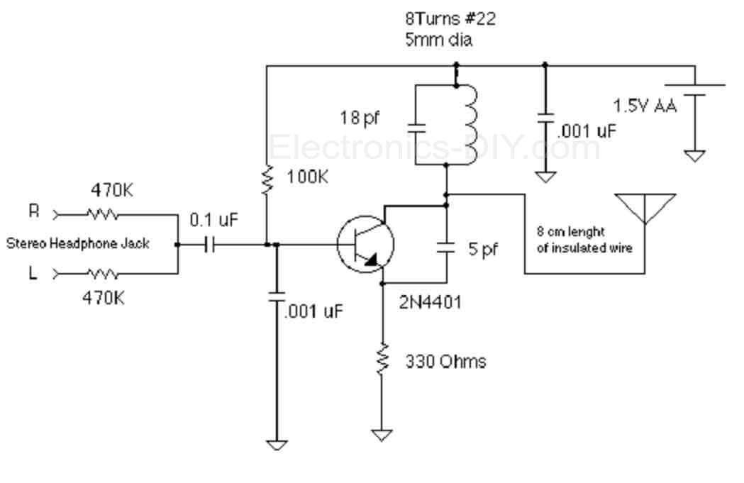
1.5 Volt Tracking Transmitter:
1.5 Volt Tracking Transmitter 2:
2N2222 40 Meter CW / DSB Tranceiver:
30 Meter QRP Transmitter for Morse Code:
4 Transistor Tracking Transmitter:
433MHz Transmitter using SAW Resonator:
7Mhz AM/CW Amateur Radio Transmitter:
7MHz SSB Transceiver: Circuit digram and brief description of 7MHz SSB Transceiver for Hams. The circuit is designed around two numbers of MC1496. It can push around 80 Watts with IRF840 in the final. You can down load HTML version or the printer friendly word document.
807 and 1625 Valves: data on vacuum tubes 807 and 1625 used in ham radio transmitters. Describes various pin voltages and different operation modes.
AM DSB Transmitter for Hams: circuit diagram of simple double side band suppressed carrier (DSBSC) transmitter for hams. Circuit uses crystal oscillator, crystal can be switched for multi band operation. .
AM oscillator for Wireless Microphones:
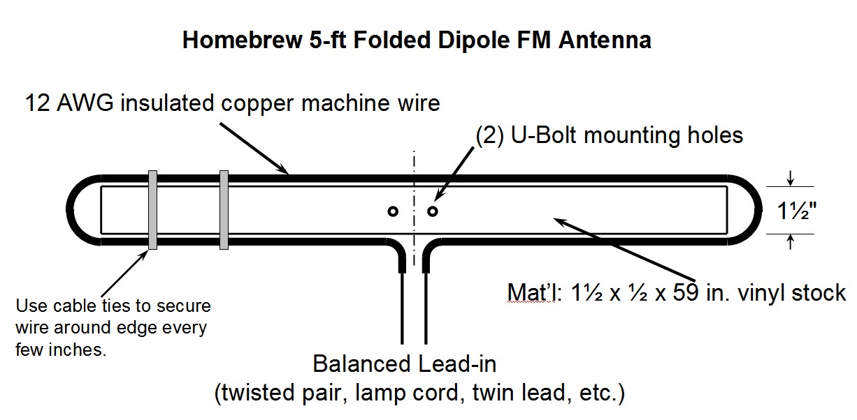
Antennas for Ham Transmitters: Describes how to construct various type of antenna for Ham Radio Transmitters.
Basic RF Transmitter for PIR Sensors:
Battery operated FM rebroadcast transmitter : Gives you 10 to 20 meters range and runs for months on a single penlight cell.
Ceramic Filter BFO: Receive SSB and CW transmissions on your BC receiver. Simple BFO is build around 455 KHz Ceramic Filter.
Crystal Controlled FM Transmitter:
Current Transmitter With Linear Voltage Transfer Rejects Ground Noise: 08/07/00 Electronic Design - Ideas for Design / Many systems use current signals to control remote instruments. The advantage of this method is the ability to operate with two remotely connected power supplies even if their grounds are not the same. In these cases, it's necessary for the output. . .
Design of Brookdale AT Volt Repeater System Exciter: uses a pair of Hamtronics model TA4512-watt narrow-band FM voice transmitters to develop video and audio carriers on439.250 MHz and443.750 MHz
Easy 2 Meter Transmitter: This project is a simple transmitter using only one crystal and will cover 145.00 to 146.00 MHz. The crystal is a 44.9333 MHz crystal for 145.500 receive, as used in the Trio (Kenwood) 2200, PYE, Motorolla, Tait equipment, to name but four. The frequency of the crystal is not critical as almost any other xtal for the 2-meter band will function
Experimental Data Transmitter for Fiber optics:
FM Beacon Transmitter (88 108 MHz): This circuit will transmit a continuous audio tone on the FM broadcast band (88-108 MHz) which could used for remote control or security purposes. Circuit draws about30 mA from a 6-9 volt battery and can be received to about100 yards.
FM Broadcast Audio Transmitter : Monophonic FM band transmitter for home use.
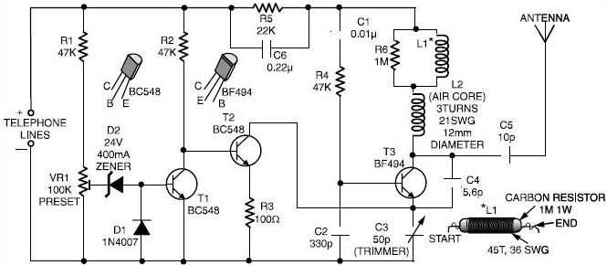
FM Radio Telephone Transmitter:
FM Radio Transmitters With OpAmp :
Four Channel Wireless Transmitter & Receiver:
Four Transistor Tracking Transmitter:
Frequency Agile 80m CW QRP Transmitter:
Infra / Radio Remote Control Transmitter / Receiver:
Infrared Transmitter and Receiver Schematic Diagrams:
Infrared Transmitter for Audio: (Amplitude Modulated IR)
Li'l 7 AM Transmitter Schematic:
Micro Power AM Broadcast Transmitters: In this circuit, a 74HC14 hex Schmitt trigger inverter is used as a square wave oscillator to drive a small signal transistor in a Class C amplifier configuration. The oscillator frequency can be either fixed by a crystal or made adjustable VFO with a capacitor/resistor combination.
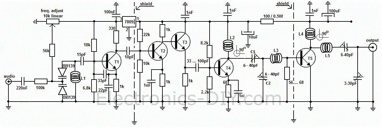
MicroPower FM Broadcasting Circuits:
Miniature MW Transmitter: circuit diagram of simple medium wave transmitter using BF494B. This simple transmitter have a range of 200 meters. .
MINIATURE TRANSMITTER: What can I say about this circuit except brilliant I have actually built this one and was very impressed, I built it using leaded components maybe one day try a bit of smd make it even smaller, problems needs a big Ariel to transmit over any great distance.
One Valve 3.5MH CW Transmitter:
QRP Keyer: very simple keyer circuit using only one transistor.
Small circuit forms programmable 4 to 20 mtransmitter: 04/17/03 EDN-Design Ideas / One of the key challenges in the design of 4 to 20-mA current transmitters is the voltage-to-current conversion stage. Conventional transmitters use multiple op amps and transistors to perform the conversion function. These approaches have been around for a long time, but they are usually inflexible, have poor power efficiency, and have limited current compliance...
Surveillance Transmitter Detector: This circuit can be used to "sweep" an area or room and will indicate if a surveillance device is operative. The problem in making a suitable a detector is to get its sensitivity just right, Too much sensitivity and it will respond to radio broadcasts, too little, and nothing will be heard.
T Volt Transmitter: allows you to send video to any television in the house, Poptronix kit circuit
Transmitter senses triple relative humidity figures: 09/26/2002 EDN - Design Ideas / The circuit in Figure 1 is a triple, relative-humidity sensor and radio transmitter. Sensors 1 and 2 form two gated oscillators with natural frequencies of 10 and 5 kHz, respectively, at relative humidity of 50%. The gated oscillators use variable resistances R2 and R3, respectively. Together, these two oscillators generate FSK-modulated outputs at output of IC1B, Pin 6..
Two Transistor FM Transmitters:
VHF / UHF T Volt Modulator: Elektor January1985
VHF Audio Video Transmitter: This circuit is a TV transmitter on VHF band.
Video / Audio Wireless Transmitter: circuit diagram and project description
Video to RF Modulator: This circuit is a RF modulator which can be used for modeling of video signal.
Video/Audio Wireless Transmitter:
Wireless IR headphone Transmitter:
Wireless Microphone Transmitter:


