Saturday, June 28, 2014

Single transistor Miniature FM transmitter with VCO


This simple transmitter allows you to broadcast on FM radio band (VHF) 87.5 - 108 MHz. It consists of a simple oscillator with silicon planar RF PNP transistor. Directly to the oscillator an antenna is connected. Due to the large amplitude of RF voltage is sufficient antenna length of about 5-10 cm. I used insulated 7cm long copper wire 1mm diameter. I eliminated the tuning capacitor, which is usual for most bugs and miniature transmitters, because this greatly complicates the tuning. From my own experience I know that if you get closer to such capacitor, the operating frequency is changed. That's why I chose to use the voltage tuning using the Voltage Controlled Oscillator (VCO). Instead of tuning capacitor the varicap (capacitance diode) is used, which changes its capacity by changing the reverse DC voltage. We can tune the operating frequency by changing the DC voltage using the trimmer P1. Varicap also provides frequency modulation.

Tuning: Set P1 to the center. Turn on the FM radio and tune it to an unoccupied frequency in the 87.5 - 108 MHz band. You will hear a noise. Turn on the transmitter and the first tune the operating frequency of roughly by stretching turns in the coil L1. Then fine-tune the frequency using P1. Proper tuning is indicated by the radio getting silent. You can then connect audio source to the input (such as cassette player, CD or MP3 player, record player, audio output of PC or laptop, etc.). It is also possible to tune while already connected to the signal source. The circuit can be powered from 5V USB port available on your PC or laptop.


Inductor L1 is airborne and has six turns of 0.5 mm diameter wire wound on 3 mm diameter. Varicap is arbitrary, which covers the range of about 5-20pF, such as BB105, KB105, KB109. I used the varicap KB109G made by Tesla with yellow paint on the cathode. The transistor is a high-frequency planar PNP type, for example, BF970, BF979, or simmilar. You can also use a transistor with different type of case. The disadvantage of the circuit is sensitivy to changes in supply voltage (it is changing the varicap voltage and thus the operating frequency). The antenna is connected directly to the oscillator, so if you touch it or placing it near the conductive object, the frequency shifts. At its simplicity, however, the circuit works surprisingly well and the range is about 20 to 100 meters. You can use power supply of 5-12V or a battery. There should be no ripple in the supply voltage, otherwise it may be heard in the receiver.

     Warning: Broadcasting on VHF-FM band may be illegal in your country. Author does not take any responsibility for your possible legal penalties for illegal broadcast or due to abuse of the bug for illegal purposes! Everything you do at your own risk.


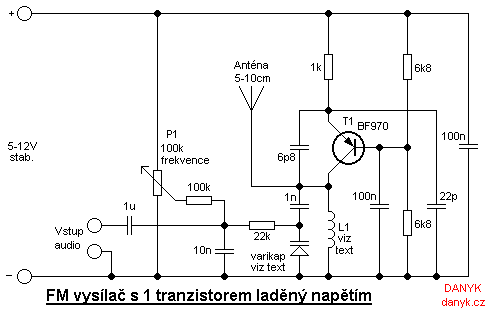
The schematic of the Single transistor Miniature FM transmitter with VCO

88-108 MHz FM covert listening device (bug)


This is a simple listening bug. The signal can be tuned on any FM radio. The first transistor (in the circuit diagram on the left) works as an oscillator (in Colpitts connection), the frequency depends on: trimmer capacitor, inductor (with 4 turns wound on 5mm diameter, no core), varicap and capacitor between collector and emitter of the first transistor. Low frequency signal from the electret microphone affects varicap voltage and thus its capacity. Varicap affectc the oscillator frequency and thus modulates the carrier wave. The second transistor acts as an amplifier and also contributes to separation of the antenna from the oscillator, thereby improving the frequency stability.


How to use the bug: Turn on the FM radio and connect the bug to voltage 9-12 VDC and try to tune the radio frequency bugs. If the bug is near the radio and the radio is well tuned, you can hear feedback whistling. Range of this bug is about 20 to 100m (66 to 330 feet). The antenna is cca 10 - 30cm (1/3 - 1 feet) wire.

  Warning: Broadcasting on VHF-FM band may be illegal in your country. Author does not take any responsibility for your possible legal penalties for illegal broadcast or due to abuse of the bug for illegal purposes! Everything you do at your own risk.

5W1.5W 88-108Mhz FM Transmitter 14MHz (20m) AM Transmitter


This transmitter is designed to transmit sound (music, speech, ...) at frequencies 88-108MHz with a frequency modulation (FM). Its RF power is about 1.5 W. The first transistor is used as an RF oscillator. Varicap allows the oscillator frequency shifting and thus its frequency modulation and frequency tuning via potentiometer. Varicap may not be the BB105, it can be BB409, BB109G, KB109G or other type. The second transistor is the power output stage. The output signal goes through a filter to remove harmonics and then it enters antenna, eg dipole or Yagi antenna (it has better directivity). Power transistor is on the heatsink with min. 100 cm2 area. Coils are air, wire diameter of 0.6 mm wound on 5 mm.

     Warning! Operating this transmitter without permission is illegal.


1.5W 88-108Mhz FM power Transmitter schematic (note: "z" means number of turns)

Saturday, June 21, 2014

Simple FM Receiver


Frequency modulation is used in radio broadcast in the 88-108MHz VHF band. This bandwidth range is marked as FM on the band scales of radio receivers, and the devices that are able to receive such signals are called FM receivers. The FM radio transmitter has a 200kHz wide channel. The maximum audio frequency transmitted in FM is 15 kHz as compared to 4.5 kHz in AM. This allows much larger range of frequencies to be transferred in FM and thus the quality of FM transmission is significantly higher than of AM transmission.


Here’s a simple FM receiver with minimum components for local FM reception. Transistor BF495 (T2), together with a 10k resistor (R1), coil L, 22pF variable capacitor (VC), and internal capacitances of transistor BF494 (T1), comprises the Colpitts oscillator. The resonance frequency of this oscillator is set by trimmer VC to the frequency of the transmitting station that we wish to listen. That is, it has to be tuned between 88 and 108 MHz. The information signal used in the transmitter to perform the modulation is extracted on resistor R1 and fed to the audio amplifier over a 220nF coupling capacitor (C1).

You should be able to change the capacitance of the variable capacitor from a couple of picofarads to about 20 pF. So, a 22pF trimmer is a good choice to be used as VC in the circuit. It is readily available in the market. If you are using some other capacitor that has a larger capacitance and are unable to receive the full FM bandwidth (88-108 MHz), try changing the value of VC. Its capacitance is to be determined experimentally.

The self-supporting coil L has four turns of 22 SWG enamelled copper wire, with air core having 4mm internal diameter. It can be constructed on any cylindrical object, such as pencil or pen, having a diameter of 4 mm. When the required number of turns of the coil has reached, the coil is taken off the cylinder and stretched a little so that the turns don’t touch each other.

Capacitors C3 (100nF) and C10 (100µF, 25V), together with R3 (1k), comprise a band-pass filter for very low frequencies, which is used to separate the low-frequency signal from the high-frequency signal in the receiver.You can use the telescopic antenna of any unused device. A good reception can also be obtained with a piece of isolated copper wire about 60 cm long. The optimum length of copper wire can be found experimentally.

The performance of this tiny receiver depends on several factors such as quality and turns of coil L, aerial type, and distance from FM transmitter. IC LM386 is an audio power amplifier designed for use in low-voltage consumer applications. It provides 1 to 2 watts, which is enough to drive any small-size speaker. The 22k volume control (VR) is a logarithmic potentiometer that is connected to pin 3 and the amplified output is obtained at pin 5 of IC LM386. The receiver can be operated off a 6V-9V battery.