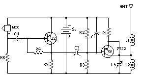
- L1 and L2 are 5 turns of 28 AWG enamel coated magnet wire wound with a inside diameter of about 4mm. The inside of a ballpoint pen works well (the plastic tube that holds the ink). Remove the form after winding then install the coil on the circuit board, being careful not to bend it.
- C5 is used for tuning. This transmitter operates on the normal broadcast frequencies (88-108MHz).
- Q1 and Q2 can also be 2N3904 or something similar.
- You can use 1/4 W resistors mounted vertically instead of 1/8 W resistors.
- You may want to bypass the battery with a .01uf capacitor.
- An antenna may not be required for operation.
For more info - http://www.aaroncake.net/circuits/fmtrans.asp
No comments:
Post a Comment